Legend
| Т | К | С2 | 03 | ОД | БЛ |
| Control circuit voltage, V | Type | Commutation current, A | Number of contacts | Ambient temperature | Modification |
|---|---|---|---|---|---|
| V Т=30 | K=Commutation | E5=5 | 2П=2 changeover contacts | 0=+60 | Л |
| П=15 | T=Current | Д1=10 | 4П=4 changeover contacts | ОД=+85 | БЛ |
| С=115 | Н=Voltage | Д2=25 | 6П=6 changeover contacts | 1=+100 | А |
| П=AC current-controlled | Д5=50 | 01=1 N/O contacts | 1Д=+125 | Г | |
| С1=100 | 02=2 N/O contacts | 1П=+150 | ГБ | ||
| С2=200 | 03=3 N/O contacts | ||||
| С4=400 | 11=1 N/O contacts | ||||
| С6=600 | 33=3 N/O contacts | ||||
| Т1=1000 |
Purpose:
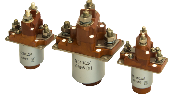
Commutation of DC circuits in aircraft electrical systems.
Technical characteristics:
| ▪ | Commutation current | 50, 100, 200, 400, 600 A |
| ▪ | Voltage in control and commutation circuit | 27 V DC |
| ▪ | Duty | continuous |
| ▪ | Current in auxiliary output circuit | 0.2 to 5 A |
| ▪ | Aviation mechanical and climatic impacts, including tropical conditions. | |
Technical characteristics of 11ОДЛ series:
| Type | ТКД 511ОДЛ |
ТКС 111ОДЛ |
ТКС 211ОДЛ |
ТКС 411ОДЛ |
ТКС 611ОДЛ |
||
|---|---|---|---|---|---|---|---|
| Control circuit | Voltage range, V | 21 - 31.5 | |||||
| Current consumption, A | 0.29 | 0.37 | 0.45 | 0.65 | 0.73 | ||
| Commutation circuit | DC voltage range, V | 18 - 31.5 | |||||
| Maximum AC voltage, V | 220 | ||||||
| AC frequency range, Hz | 50 - 1050 | ||||||
| Current range, A | 5 - 50 | 10 - 100 | 20 - 200 | 40 - 400 | 60 - 600 | ||
| Load type | Inductive | ||||||
| Overall dimensions, mm | A | 60.4 | 70.4 | 81.4 | 104.4 | 126.4 | |
| B | 38.4 | 42.4 | 50.4 | 65.4 | 78.4 | ||
| H | 90 | 100 | 117 | 137 | 148.5 | ||
| D | Ø28 | Ø33.5 | Ø44.5 | Ø56 | Ø62.5 | ||
| L | 42 | 48 | 56 | 66 | 73 | ||
| C | 2 | 2 | 2.5 | 3.5 | 4 | ||
| E | 50 | 60 | 71 | 92 | 114 | ||
| F | 28 | 32 | 40 | 53 | 66 | ||
| d | Ø4.5 2 holes |
Ø4.5 2 holes |
Ø4.5 4 holes |
Ø5.5 4 holes |
Ø5.5 4 holes |
||
| Weight, kg | 0.20 | 0.32 | 0.58 | 1.25 | 1.85 | ||
| Electric circuit diagram | 1 | 2 | 2 | 2 | 2 | ||

.93f9bd3717ca03f2236d1886812759dd266.png)
.93f9bd3717ca03f2236d1886812759dd266.png)